Activity 2.2.2 NAND logic design
Introduction
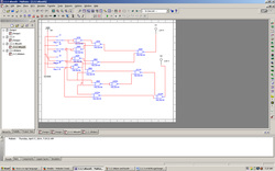
The block diagram shown below represents a voting booth monitoring system. For privacy reasons, a voting booth can only be used if the booth on either side is unoccupied. The monitoring system has four inputs and two outputs. Whenever a voting booth is occupied, the corresponding input (A, B, C, & D) is a (1). The first output, Booth, is a (1) whenever a voting booth is available. The second output, Alarm, is a (1) whenever the privacy rule is violated.
In this activity you will implement NAND only combinational logic circuits for the two outputs Booth and Alarm. These NAND only designs will be compared with the original AOI implementations in terms of efficiency and gate/IC utilization. In a future activity, these NAND only designs will be compared to the circuits implemented using only NOR gates.
Conclusion
1. For your AOI implementations, how many ICs (i.e., 74LS04, 74LS08, and 74LS32 chips) were required to implement your circuits? Note: You’re not just counting the number of gates used, but rather, the number of IC, in whole or part, that were required.
3 IC chips for the booth
2 ic chips for the alarm
2. For your NAND implementations, how many ICs (i.e., 74LS00 chips) were required to implement your circuits? Again, we are counting ICs, not gates.
2 IC chips for the booth
2 IC chips for the alar
3. In terms of hardware efficiency, how does the NAND implementation compare to the AOI implementation?
It would cost less to use NAND implementation rather than AOI implementation. You are using less chips and wires.
4. NAND gates are available with three inputs (74LS10) and four inputs (74LS20). Could either of these chips have been used for this design? If so, how would it have affected the efficiency of the design?
Yes, but you would have to use another chip. Which would decrease the efficiency.
