Project 2.2.5
Introduction
The Acme Fireplace Company has hired you to redesign the fireplace control circuit for their latest residential gas fireplace. The fireplace burner is equipped with four thermal sensors that output a logic (1) whenever a flame is present. These sensors are connected to the fireplace control circuit which outputs a (1) to the emergency cut-off valve to keep the gas flowing (i.e., a zero will turn the gas off).
The original design of the fireplace control circuit was quite simple. For the gas valve to remain on, all four sensors needed to output a logic (1). During field testing it was discovered that variations in gas pressure and humidity cause the thermal sensors to occasionally output a logic (0) even when a flame is present. This caused frequent unnecessary shut downs and constant customer dissatisfaction.
For the redesign, is has been determined that the emergency cut-off value should remain open as long as three of the four sensors indicate that a flame is present.
Additionally, the designers have asked you to add a second output indicator to the control circuit. This indicator will output a logic (1) when the four sensors do not all agree (i.e., not all on, or not all off). This indicator will be used by the service technician to diagnose whether a faulty sensor exists.
Conclusion
Using your engineering notebook/portfolio as a guide, write a conclusion (minimum 250 words) that describes the process that you used to design, simulate, and build your Fireplace Control Circuit. This conclusion must include all of your design work (i.e., truth table, K-Maps, etc.), preliminary and final schematics, parts list, and a digital photograph of your final circuit. The documentation should be complete enough that a student with a similar knowledge of digital electronics could reproduce your design without any additional assistance.
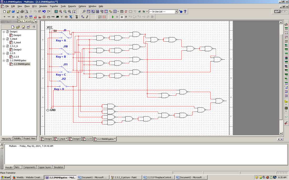
To create the Fireplace Control circuit I read over the introduction first and figured out that I had to make two separate circuits and then combine them. I had to make a cut-off valve circuit that would turn off when less than three of the four were on and a Agree/Disagree sensor circuit that would turn on unless all four of the sensors weren’t in agreement. After I figured out what the sensors had to do I created a truth table to determine when the two sensors turned on and when they turned off. Using the truth table and k-mapping I created two logic expressions: ABD+BCD+ABC+ACD and ‘A’B’C’D+ABCD. After I created the logic expressions I put them into Multisim in one single simplified NAND circuit. After I combined them on Multisim I printed it out and taped the two pages together. Using the page as a reference I crossed out wires and gates I already used as I bread boarded. While bread boarding I made sure I didn’t push the wire in too far, as this will puncture the metal sheet at the bottom, ruining the bread board.
When I finished bread boarding I tested it using 2 LEDs as the sensors and valves. For the cut-off valve I used a red LED and for the Agree/Disagree sensor I used a green LED. I used 4 different colored wires as my switches, because I didn’t have any switches, and plugged them into the power section of the breadboard when I needed them to be on.
The Acme Fireplace Company has hired you to redesign the fireplace control circuit for their latest residential gas fireplace. The fireplace burner is equipped with four thermal sensors that output a logic (1) whenever a flame is present. These sensors are connected to the fireplace control circuit which outputs a (1) to the emergency cut-off valve to keep the gas flowing (i.e., a zero will turn the gas off).
The original design of the fireplace control circuit was quite simple. For the gas valve to remain on, all four sensors needed to output a logic (1). During field testing it was discovered that variations in gas pressure and humidity cause the thermal sensors to occasionally output a logic (0) even when a flame is present. This caused frequent unnecessary shut downs and constant customer dissatisfaction.
For the redesign, is has been determined that the emergency cut-off value should remain open as long as three of the four sensors indicate that a flame is present.
Additionally, the designers have asked you to add a second output indicator to the control circuit. This indicator will output a logic (1) when the four sensors do not all agree (i.e., not all on, or not all off). This indicator will be used by the service technician to diagnose whether a faulty sensor exists.
Conclusion
Using your engineering notebook/portfolio as a guide, write a conclusion (minimum 250 words) that describes the process that you used to design, simulate, and build your Fireplace Control Circuit. This conclusion must include all of your design work (i.e., truth table, K-Maps, etc.), preliminary and final schematics, parts list, and a digital photograph of your final circuit. The documentation should be complete enough that a student with a similar knowledge of digital electronics could reproduce your design without any additional assistance.
To create the Fireplace Control circuit I read over the introduction first and figured out that I had to make two separate circuits and then combine them. I had to make a cut-off valve circuit that would turn off when less than three of the four were on and a Agree/Disagree sensor circuit that would turn on unless all four of the sensors weren’t in agreement. After I figured out what the sensors had to do I created a truth table to determine when the two sensors turned on and when they turned off. Using the truth table and k-mapping I created two logic expressions: ABD+BCD+ABC+ACD and ‘A’B’C’D+ABCD. After I created the logic expressions I put them into Multisim in one single simplified NAND circuit. After I combined them on Multisim I printed it out and taped the two pages together. Using the page as a reference I crossed out wires and gates I already used as I bread boarded. While bread boarding I made sure I didn’t push the wire in too far, as this will puncture the metal sheet at the bottom, ruining the bread board.
When I finished bread boarding I tested it using 2 LEDs as the sensors and valves. For the cut-off valve I used a red LED and for the Agree/Disagree sensor I used a green LED. I used 4 different colored wires as my switches, because I didn’t have any switches, and plugged them into the power section of the breadboard when I needed them to be on.